Schematic Design Part 1
Microcontroller Selection
I’ll start the schematic by choosing the microcontroller.
Its selection is essential to determine power supply, analog circuit, and communication.
It must be supported by the Autonomy software, so let’s check which models are supported and study their availability and prices:
- Arduino Opta - Uses the STM32H747 microcontroller at $20. No chance.
- esp32 - More affordable, but I’m paying for Wi-Fi, which I don’t need right now.
- esp8266 (node-mcu board) - A $4 board with everything I need and USB programming. However, it’s limited in terms of possible inputs and outputs.
- Mega / Due - Has far more features than I need.
- MKR Series - Wi-Fi and lots of features.
- Nano Every - €15 for a single board.
- RP2040 - A strong candidate, its board costs around $6 but has limited IO.
- STM32F103CB (Blue Pill) - The best candidate so far. It has plenty of IOs, and I can buy it for $3 in Brazil.
- STM32F411CE (Black Pill) - More expensive than the Blue Pill.
- Uno, Leonardo, Nano, Micro, Zero - Atmel microcontrollers are usually more expensive with fewer features.
Therefore, I will use the Blue Pill’s microcontroller for the development of the Lira-CLP.
General Considerations
I will use 24V power supply for all input and output circuits. I will leave all digital inputs already connected to GND, and the outputs already connected to 24V. The analog input is also connected to 24V.
The microcontroller will be isolated using a 5V-5V isolator, as well as the communication.
I will use a step-down module for which I don’t have the exact circuit, but it is based on the LM2596 regulator and is widely used. In other words, the circuit is also available if you want to use it from scratch. I’m using it because it costs less than 2 USD here in Brazil.
Digital Input
The digital input circuit using an optocoupler is quite simple and comes in many styles online. What I liked about the Small Open PLC project is the use of the input itself to power the indicator LED, but I’ll design the circuit slightly differently in a way I consider safer, adding an RC filter.
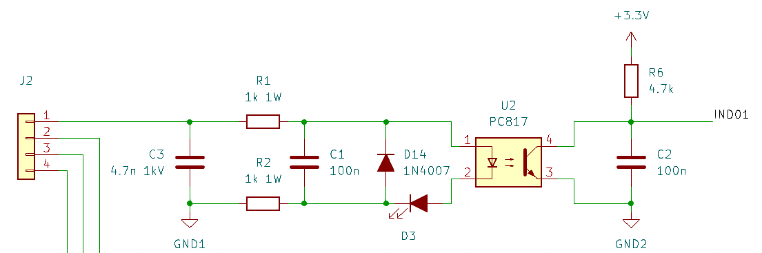
The R2 to GND helps provide better protection against surges coming from the 0V line.
I usually don’t add varistors to the inputs of equipment that connect to the panel. Often, panels lack proper protection, and the varistor on the equipment ends up protecting the entire system, which leads to the circuit burning out.
I removed the Zener to save costs, as it is not necessary.
This circuit can work with lower voltages but is designed for 24VDC.
Digital Output
To use components that I find easily in Brazil, I’m designing the outputs in source mode using the TIP125, a Darlington transistor with integrated diodes. It also has a VCE of 60V. I added an LED for indication and a resettable fuse to prevent burning out the transistor. I’m also using the 4N25 optocoupler, which has a maximum VCE of 70V.
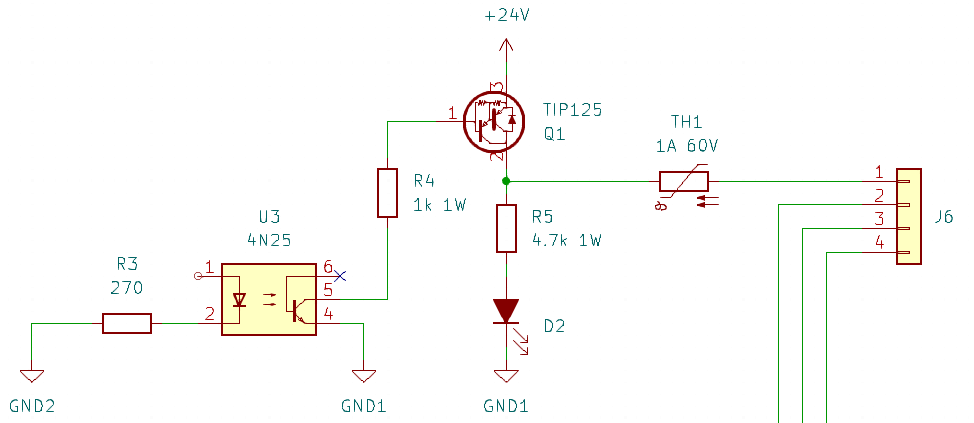
The source circuit is the one I use the most in automation, which is why I chose this version.
Analog Input
This is an experimental circuit.
For a while now, I’ve been looking for a low-cost isolated analog circuit.
Recently, while searching for ways to design the analog input, I found the LM331 from Texas Instruments, an IC that converts voltage to frequency and vice versa — perfect for use with an optocoupler.
I essentially copied the circuits from the datasheet, modifying some resistors to limit the output voltage to 3V for the microcontroller.
The modulator circuit, demodulator, and the current-to-voltage conversion are shown in the images below.
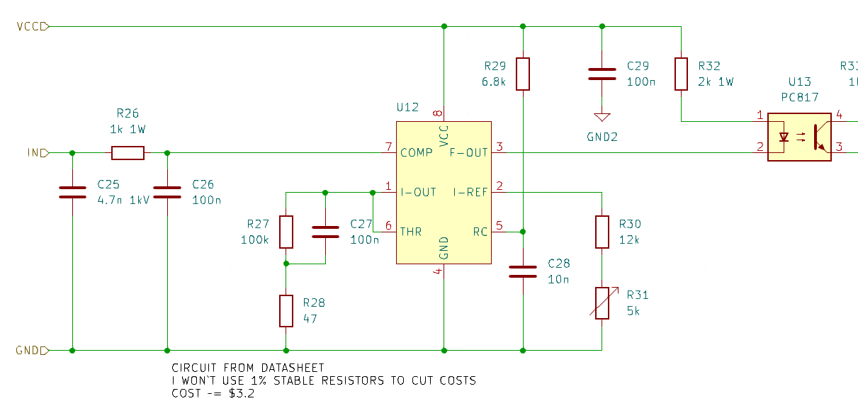 Modulator circuit.
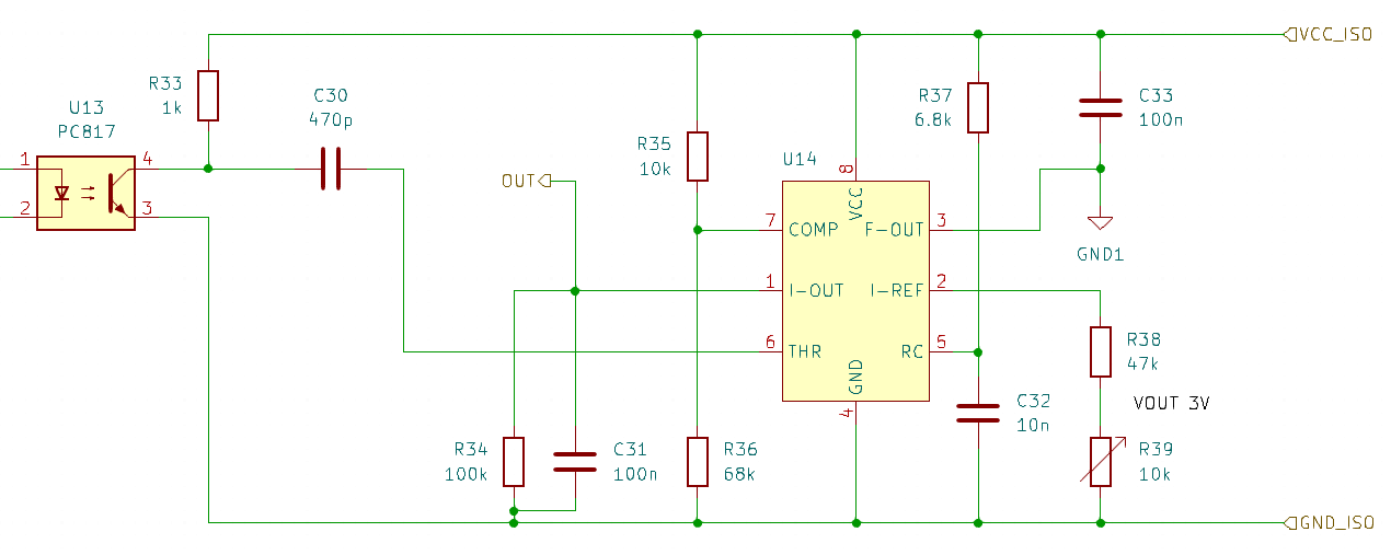 Demodulator circuit.
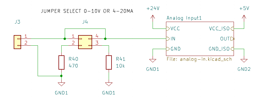 Voltage or current selection.
I won’t use precision components or high thermal stability at first. However, depending on the results, they may become necessary.
I didn’t add protection because the input circuit already has an RC filter, the power supply will include a TVS for supply protection, and the LM331 supports up to 40V maximum.
The circuit is designed to operate with 0-10V or 0-20mA and a frequency of up to 10kHz.
The best part is that the BOM cost of this circuit is around $3, which is less than many isolated op-amps on the market.
This is also a great circuit for transmitting analog signals through fiber optics.
Power Supply
I’m using a step-down converter for 5V and isolating the 5V supply for the microcontroller.
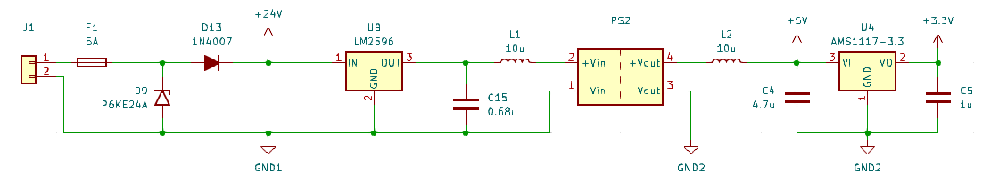
The capacitance and inductor values follow the datasheet recommendations. In this case, I used the datasheet of the MEE1S0505SC from Murata.
The step-down already includes the necessary capacitors.
The schematic is almost complete. I will still work on the microcontroller section and the RS485 communication in the next post.
The GitHub repository for this project has already been released.
I will compile a Design Guide after development, including calculations and relevant details. I also have the simulation circuits using TINA-TI available in this project’s GitHub repository.
If you have any questions or recommendations, feel free to contact me via email.